
Servo Drive
In industrial processes, a motion control system is used to move a particular load in a controlled manner. Pneumatic, hydraulic, or electromechanical actuation technology may be used in these systems. The actuator type, which is a device that provides the energy to move the load, is chosen based on power, velocity, accuracy, and cost considerations. In an electromechanical system, a motor is used as the actuator, which produces power by interacting with electromagnetic fields. These motors can move in either a rotary or a linear configuration. Such systems are adaptable, efficient, affordable, and commonly used in applications requiring high accuracy, low to medium power, and high speed.
Open Loop vs Closed Loop
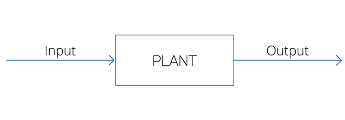
Motion Control Systems are classified into two main types, Open Loop and Closed Loop Systems. An open-loop system operates on time-dependent inputs and does not require any feedback from the output (See Fig. 1). Those systems are simple, require low maintenance, and cost-effective. Some examples are washing machines, toasters, hand driers, and more.
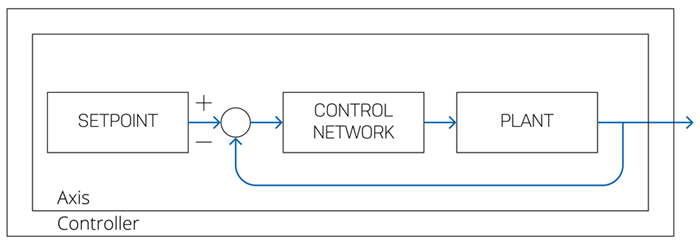
In a closed-loop system, a feedback tracking device, most commonly an optical encoder is used to transmit a signal back to the controller to account for expected errors. The controller evaluates the error between the control input (Reference command) and the actual feedback of the mechanism or the control shaft and adjusts the system behavior accordingly (See Fig. 2).

Figure 1. Open loop system

Figure 2. Closed loop system
The following figure is a typical configuration of a motion control system consists of a motion controller, a servo drive, a motor with a feedback device, and a load.
Each of the following products has a distinct role in achieving precise motor control and increasing system efficiency. Having this figure in our minds, let's break the system into single components and discuss each part of the system individually.

Figure 3. Motion Control System
Load
The load or the final moving part is the starting point when designing a motion control system. Before choosing any components, it is crucial to understand the application architecture as it largely determines the performance of the machine or the automated system. For instance, it is critical to predetermine the required motion properties, such as jerks, accelerations, decelerations, velocities, and positions to choose the right motor and drive. Disturbances and instabilities in the system due to moving mechanical parts like bearings, gearboxes, speed reducers, ball screws, and various linkages, will affect the choice of a control system and the required motion controller performance. High detailed application requirements and specifications information will result in an efficient and cost-effective motion control system.
Feedback Devices
In motion control systems, feedback devices are used to monitor the position and the velocity of a motor or a load. Once such information is available, the motion controller can then account for errors in the system and react accordingly. There are two main types of encoder: absolute and incremental, which can be used in rotary and linear motors. Absolute encoders are feedback devices, which can store the definitive position information internally. They output unique words or bits for each position and enable to maintain the position information when power is removed from the encoder. Incremental encoders, unlike absolute encoders, use light pulses to indicate position changes. They typically consist of two channels with shifted phases, which allows determining the direction of the movement. Unlike absolute encoders, they are unable to store position information after power off; therefore, they are usually combined with an absolute indicator such as a limit switch or a hard stop to determine the initial position. A third channel in the encoder, typically referred to as the Z index pulse may also be used to determine the shaft’s starting position.
Motors
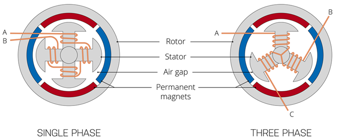
Motors are electrical machines that convert the current and the voltage that comes from the drive into mechanical motion. Motors can be either brushed or brushless, rotary, or linear. DC Motors can generally be divided into two categories; single-phase brushed motors and three-phase brushless motors (See Fig. 4). Single-phase motors use two power wires: hot and neutral, whereas three-phase motors use three wires and are driven by three alternating currents of the same frequency.

Figure 4. Single Phase vs Three Phase motor
Brushed DC
Motors are electrical machines that convert the current and the voltage that comes from the drive into mechanical motion. Motors can be either brushed or brushless, rotary, or linear. DC Motors can generally be divided into two categories; single-phase brushed motors and three-phase brushless motors (See Fig. 4). Single-phase motors use two power wires: hot and neutral, whereas three-phase motors use three wires and are driven by three alternating currents of the same frequency.
Voice Coil
Voice coil motors are linear DC Motors that consist of two separate parts: a magnetic housing and a coil. The direction of the motion can be controlled by applying a voltage across the terminals. Reversing the polarity of the applied voltage will cause a motion in the opposite direction. Prodrive Technologies has developed its voice coil motors, which are designed for high precision motion and force control while allowing movement in 6 degrees of freedom. Different form factors are available, in both rectangular and cylindrical shapes with different motor constants and optimized steepness.
Brushless DC
Unlike Brushed DC motors, brushless DC (BLDC) Motors, as the name implies, do not use mechanical brushes to establish contact with the coils. The coils are placed on the stator, and the magnets are mounted on the rotor. The number of phases matches the number of windings on the stator. This way, the current is applied directly to the coil, and an electronic current-phase commutation is required to efficiently operate the motor. BL Motors have a higher power-to-weight ratio, better heat dissipation, and require less maintenance than brushed motors.
Linear
Linear motors, like rotary motors, have a stator and a rotor. However, the stator and the rotor are “unrolled”, therefore, producing a linear force rather than a rotational torque. Linear motors are used in direct drive applications where the speed and accuracy specifications exceed the capabilities of a rotary motor and ball screw. Prodrive Technologies develops and manufactures linear motors for wide application requirements, including Iron core, Ironless, and vacuum linear motors.
Servo Drive
A servo drive, also known as a servo amplifier, is the linkage between the controller and the motor and responsible for powering the servo motor in the system. The servo drive is a critical component in assessing the servo system's performance. Servo drives have several advantages over straight power amplifiers for automatic machining systems, including superior positioning, speed, and motion control. In essence, the servo drive is responsible to convert the controller's low-power command signals into high-power voltage and current for the motor.
Motion Controller
Motion controllers are devices, which are responsible for the control of a motion system. In general, motion controllers run software to command movements on automated pieces of machinery. They are typically referred to as the “brain” of a motion control system. Motion controllers are often PC-based, providing a graphical user interface for ease of use. In motion control systems, the controller is also referred to as the master device, which provides the control algorithms, motion profiles, target positions, and processes the required motion trajectories. Motion controllers are capable of managing several slaves devices on the same network, such as I/O devices and drives, and, therefore, manage complex multi-axis systems.